Bartop Arcade – part 1

A Facebook post from a friend of mine triggered a new project… how cool it would be to build an old school arcade machine? I did some internet digging and found some examples, some plans, and even step-by-step tutorials. I already had a Raspberry Pi B which was unused, so it would be a cool way to put it to use.

There is a lot of info online, but the most important resources I’ve found to be quite helpful were a site with free plans, some videos and an Instructable  (check Resources below). I soon found out about Retropie (also link below), and burning an SD card with an image was quite easy.
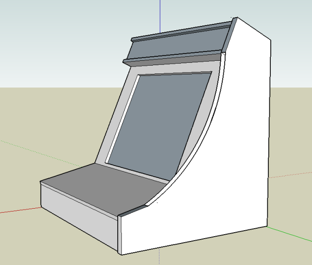
1 – Design

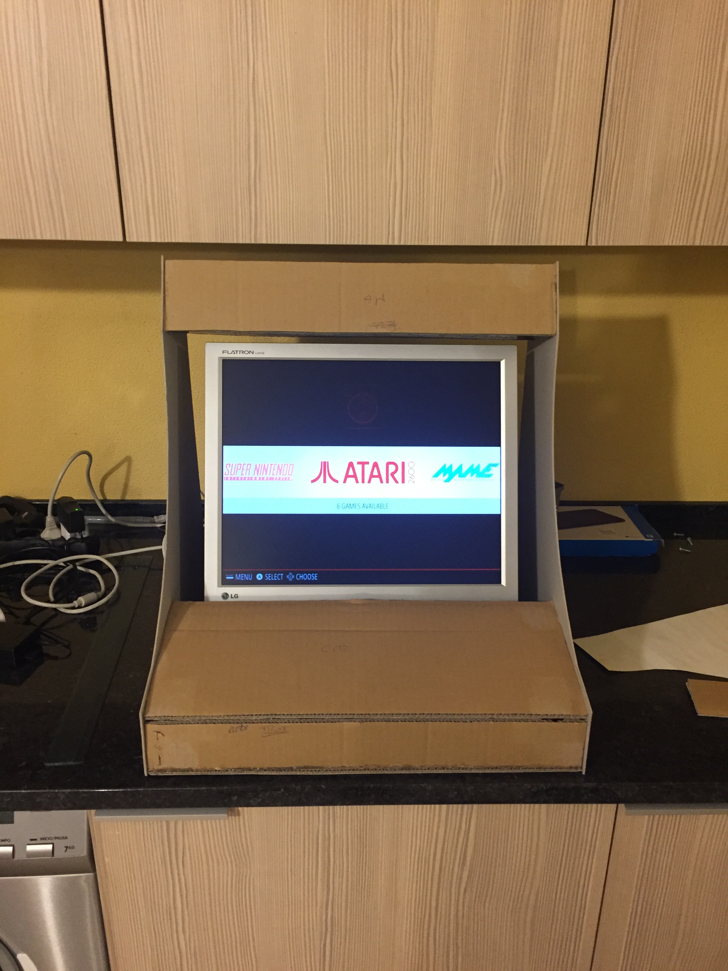
First challenge…All the free plans I’ve found out would not fit the area I designated for the Bartop…so I went Rambo on it and designed my own plans in SketchUp! After some iterations and cardboard trials and I’ve finally found out a design which would work for me.

The design requirements were:

  • Compact design
  • Maximum height of 55 cm, in order to fit between the countertop and the cabinets
  • Reduce the MDF cost to a minimum
  • 90º cuts when possible, as my woodoworking skill are not the best
  • It had to had some T-moulding for that old-school feel, but again reducing costs to a minimum

If you want the plans send me an email and I’ll get back at you!

Bartop.png

IMG_0488.JPG

2 – CPU+Display+Sound

As mentioned before, I wanted to use the RPi I’ve had with no special use, so the CPU was decided. I’ve burned a Retropie image to an SD Card and soon I had this running. Some games lag a little bit, but the NEO-GEO, SNES and MegaDrive work like a charm.

For the display, I’ve found a cheap used 19′ 4:3 display online, but it was only VGA. The output of the RPi is HDMI, so I needed a converter. Here an important tip, if you need a converter go towards a powered one, passive often don’t work properly.

sku_71816_1

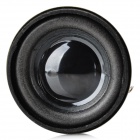
Having this figured out, next step was the sound: no gaming machine is good if it’s silent… The RPi only has low-power outputs, so an amp was required. I found one really cheap online and also some speakers. I’ve used some parts I already had (USB cable for power + 3.5mm stereo jack with cable), and after some time soldering I got myself an audio system… It’s far from being and audiophile setup, but for what I’ve wanted and the money I was willing to spend, it worked like a charm.

1437965370647-p-2835870sku_378632_1_small.jpg


In the end I’ll be adding a list of the things I’ve purchased, where did I bought it from and the costs.

3 – MDF

My woodworking skills are not the best… that being said, I wanted to make my life the easiest possible, and keep the costs low. This lead me to think mostly on 1 mm thick MDF except on the sides. Since I wanted to add T-Moulding, and also to enhance the structure of the whole thing as it’s bound for some abuse, I’ve thought on using 16mm. After some Tetris planing in order to optimize the use of the MDF boards, I’ve ended out with a setup that only required the following boards:


(to be continued… The planning phase is over and I have most of the stuff figured it out, nevertheless I’ll keep this project on hold for a little bit… I have several other which require my attention and it’s better to finish the pending ones before starting new ventures…)


P.S.: For those who want such a DIY, but don’t want to mess with the woodworking, search on eBay and you’ll find stuff like this for about 150€ or less… I just prefer to build my own, as nothing beats the “I built this!” feeling, even if the final outcome is not as perfect… 😀


s-l1600

Resources:

  • Pretty cool Instructables post: link
  • Free plans online: link
  • Cool build with plans to buy, but great videos with some useful techniques: link
  • Retropie webpage: link

Take care and be safe out there…

AGT

R2-D2 key storage – part 2

Hey,

So after a looooot of masking and correcting lines, I finally finished the key storage.

Note to myself, next time sand the whole thing down first, properly primer it and start working with a perfectly flat surface…that would help a lot as making straight lines in a textured surface is a major pain in the neck…

major-pleasure

(Major pain…another HIMYM reference, for those who get it…)

I’ve given it some coats of mate varnish and covered the inside with soft padding (the one normally used below furniture or in cabinet doors/drawers to soften up the closing), and that was it. Done!

On to the next project! 🙂

Take care and be safe out there…

Star Wars Cabinet

Ok, so I’m geek… You’ve probably already noticed that. 🙂 Oh, and I simply LOOVE the Star Wars universe…which you should already have noticed also..

I was gathering a bit of a collection, and I wanted a place to display all my stuff (and also protect it from my baby, and protect my baby from it – small easy-braking plastic parts are always a concern when you have a toddler wandering around).

Our office is quite small! When we purchased the house I imagined it to be the biggest room, but it ended up as being the smallest…funny how things turn out! We had to think on how to properly fit everything we wanted without making it unusable or too “crowded”. I like the end-result, but some more real estate would be nice…maybe next time, when I earn enough to purchase a house with a proper man-cave.

Well, let’s get back on-topic. As always, money is a concern, so an IKEA Besta was the solution for the cabinet. I’ve ordered some tempered glass doors cut to fit, and after some DIY tweaking I got quite a nice place to show my stuff.

Under the desk I have a switch, which transforms the office into “non-work mode”: it turns on indirect lighting on the end of the desk, a Batman sign on the wall, and I wanted also this to light the cabinet. I had some LED strips from a previous project (a cloud lamp for the baby room and also the Batman sign, soon to be featured in the blog), so the light source was chosen.

After some time working all the cabling, the end result was quite satisfying… Since I already had the led strip, the only cost was with the electrical cable (~6€), the led strip adapters (~4€) and a 12V 2.5A Power supply (~7€)! Happy times!

In the shelves you can check out some past and future projets…

Take care and be safe out there…

AGT

R2-D2 key storage – part 1

One thing we’ve been lacking since day one at our house is a proper key storage. Currently they are all inside a drawer, and every time we need to find a specific key it’s a pain.

So, after giving it some thought and not really liking the options my local hardware shop had for me, I had an idea.

Chinese shops use to have (at least in Portugal) small wood boxes with no finish, just raw wood…why not use one of those to store the keys? 

Ok, so the base solution is found…but I’m not using this as raw wood, I have to give it a protective coat of paint or varnish.

Then internal unease arises…There is no way I’m putting a basic coat of paint without any kind of customization… I’ve got to add some personal feel to it.

My brain starts working and after a quick research I found the answer. Why not make a R2-D2 themed box? I’ve seen some lunch boxes which transform the cilindrical form of the R2 into a box-shape, maintaining the R2 feel.

After some googling around, I’ve found these instructions to make an R2 paper robot. These gave me the ground base I needed to start working (credits in the picture).

  
Then painting stage begins. I have to start by saying that my painting skills are rather basic, and I did not wanted to use an airbrush or spray. I had some vinyl water based paint around – from Titan paints, really cool stuff – and I also wanted to make this project as cost effective as possible, so this was my weapon of choice. Just needed to buy one black bottle and one grey, since I already had cyan blue and white.

I wanted to base the whole artistic part with straight lines, so my initial thought was to use masking tape it order to guide the paint. I dont trust my skills to do decent curve lines… Though, since the wood surface is a bit rough, the masking tape did not attach perfectly and it caused a lot of paint bleeding in the first tries. Eventually I’ve solved the issue by giving a first coat of the base color before painting the top color. The base color seals the masking tape, not allowing the top color bleeding. The process takes twice the time, but the end result is worth it. Since drying times are of a couple of minutes, it takes some time but Its feasible. The last few nights after the baby is asleep had been dedicated to this.

I’m currently finishing the (first) front panel. I know it’s not very detailed, but it’s giving me way too much trouble as it is…and I’m kind of happy with the way it’s coming. 

The first shapes took me some extra time to fine tune as some were crooked and had to be corrected… I’m hoping the following ones can be quicker as I perfect the process.


More to come soon.

BTW, 3M masking tape is really great… 
Take care out there…

AGT


Word Clock

This project took me forever to finish… but still it is one of the best looking ones I’ve built so far.

Around 2012 some friends introduced me to the Biegert&Funk QLOCKTWO. I found this to be pretty awesome, and soon I was started thinking how hard could it be to build one of my own…

large-black-pepper-b
QLOCKTWO

I think it was by this time that I’ve found out about Instructables, and I’ve found this one.

As Barney Stinson from How I Met Your Mother would say:

how-i-met-your-mother-challenge-accepted

I’ve started building the clock following the steps, but soon enough I’ve started making some changes:

  • Printed a portuguese word clock layout in transparent acetate sheets in a local Staples, and stack them up for a dark professional look.
  • Used the original IKEA RIBBA frame, as it was a pretty good enclosure for this project, and cut a bright green passepartout out of a sheet of thick paper.
  • Used a perforated prototyping board for the shifters and the amplifiers, with lot’s of wiring…not the most professional look, but it was cheap and got the job done.
  • The support for the leds and electronics was a piece of thick cardboard.
  • Used an Arduino UNO, since I didn’t want to fiddle around with oscillators, etc, but mounted a power regulator so that the UNO and the Amplifier and Registers would get a stable voltage.

It took me forever to solder the Leds to the resistors…

IMG_1470.JPG
Led to resistor soldering process

When finally I’ve ended all the soldering, I have to say that I ran out of motivation juice, and the project stood still for a while… until I thought to myself that I was not going to be one of those guys who start a bunch of things but don’t finish them.

After a lot of soldering (and patience) I’ve ended up with this:

IMG_1502.JPG
Final hairy connections done.

I know, it’s not pretty…but hey, it works. 🙂

The Arduino code was relatively easy to write, and soon enough I’ve ended up with my own Word Clock. YAY!

I think the outside looks a lot better than its guts, but after 3 years it still works.

IMG_1499
Backside with the hours and minutes set buttons

Here it is in its final position, close to my Batman vehicles and the first version of the Iron Man Arc Reactor (more on this later…).

Finished project!

Take care, and be safe out there!
AGT